Layout Frontends
A frontend is the layer that turns a layout, however you drew it, into
the engine-agnostic Component that every solver
consumes. It reads the polygons on each technology layer, extrudes them to the
z-heights and materials the Technology and Materials defines, and auto-detects the
ports from the layout’s pin/DevRec conventions.
layout source                       frontend                     Component
─────────────                       ────────                     ─────────
gdsfactory component  ─────▶  layout.gdsfactory.from_gdsfactory  ─┐
SiEPIC / KLayout cell ─────▶  lyprocessor.load_cell              ─┤─▶  Component  ─▶  get_solver(...)
raw .gds (any tool)   ─────▶      + load_component_from_tech     ─┤       (polygons +
litho-predicted .gds  ─────▶  lyprocessor.load_device (PreFab)   ─┘        ports + bounds)
The Component is the boundary: your frontend choice and your engine choice are independent. The same y-branch reaches beamz, tidy3d, and Lumerical whether it came from gdsfactory or a foundry PDK; conversely one frontend feeds every engine. The worked example is 08 · Any EDA in, any engine out.
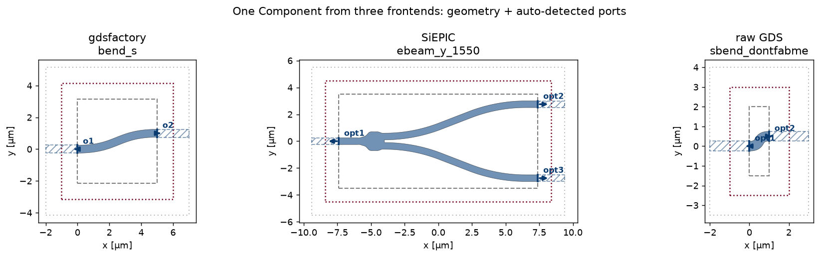
One Component, three frontends. Each device carries device polygons,
auto-detected ports (arrows), the DevRec bounds, and, given a
SimulationSpec, the FDTD region. Downstream everything is identical.
Built-in frontends
gdsfactory
gdsfactory (>= 9) builds
components parametrically in Python. from_gdsfactory()
reads the polygons on each technology layer and lifts the gdsfactory ports into
gds_fdtd ports:
import gdsfactory as gf
from gds_fdtd.layout.gdsfactory import from_gdsfactory
from gds_fdtd.technology import Technology

tech = Technology.from_yaml("tech.yaml")
gf.gpdk.PDK.activate()
component = from_gdsfactory(gf.components.mmi1x2(), tech)
SiEPIC / KLayout
A cell from a KLayout/SiEPIC foundry PDK, the path most silicon-photonics
tapeouts use. load_cell() opens the layout;
load_component_from_tech() extrudes it against the
technology. Ports come from the SiEPIC pin + DevRec layers:
import os
import siepic_ebeam_pdk as pdk
from gds_fdtd.lyprocessor import load_cell
from gds_fdtd.simprocessor import load_component_from_tech

gds = os.path.join(os.path.dirname(pdk.__file__), "gds", "EBeam", "ebeam_y_1550.gds")
cell, layout = load_cell(gds, top_cell="ebeam_y_1550")
component = load_component_from_tech(cell=cell, tech=tech)
Raw GDS
No PDK, no framework, any .gds from any tool. As long as its polygons land
on the technology’s device / pin / DevRec layers, ports are detected the same
way:
cell, layout = load_cell("my_layout.gds", top_cell="my_cell")
component = load_component_from_tech(cell=cell, tech=tech)
PreFab (lithography prediction)
PreFab predicts how a nanofabrication
process will actually print your design (corner rounding, proximity effects).
load_device() runs the model, writes a
<cell>_predicted.gds, and loads it like any other GDS, so the litho-predicted
shape flows through the identical path (needs a PreFab account):
from gds_fdtd.lyprocessor import load_device

predicted = load_device(
    "my_design.gds", tech=tech, top_cell="my_cell",
    prefab_model="ANT_NanoSOI_ANF1_d10", output_dir="out/",
)
What every frontend produces
A frontend’s only job is to return a Component with
three things:
structuresA flat list of
Structure, each a 2-D polygon extruded in z, tagged by role:"device"(your patterned layers),"substrate", and"superstrate"(the backgrounds, filled from the technology). Each carries its GDSlayer, z-extent, and the resolvedmaterial.portsA list of
Port, each with a name, µmcenter[x, y, z],width, and a snappeddirection(0/90/180/270°). These are where the solver launches and collects modes.boundsA
Region, the simulation extent (from the DevRec layer for the GDS frontends).
Write your own frontend
To support a tool that is not listed above (a different layout library, a
procedural generator, an in-house format), write a function that produces the
three objects above. The two reference implementations to copy are
load_component_from_tech() and
from_gdsfactory().
The example below builds a 5 µm straight waveguide entirely by hand, no GDS, no
layout library, and it runs on any engine. It uses the technology’s own
z-heights and materials (via to_solver_dict())
so a custom frontend needs to supply only the polygons and ports:
from gds_fdtd.geometry import Component, Port, Region, Structure
from gds_fdtd.technology import Technology
from gds_fdtd.solvers import get_solver
from gds_fdtd.spec import SimulationSpec

tech = Technology.from_yaml("tech.yaml")
layers = tech.to_solver_dict()          # device / substrate / superstrate as dicts
dev, sub, sup = layers["device"][0], layers["substrate"][0], layers["superstrate"][0]

z_center = dev["z_base"] + dev["z_span"] / 2
background = [[-2.0, -3.0], [7.0, -3.0], [7.0, 3.0], [-2.0, 3.0]]
core = [[0.0, -0.25], [5.0, -0.25], [5.0, 0.25], [0.0, 0.25]]   # 5 x 0.5 um strip

structures = [
    Structure(name="core", polygon=core, z_base=dev["z_base"], z_span=dev["z_span"],
              material=dev["material"], layer=list(dev["layer"])),        # role="device" (default)
    Structure(name="sub", polygon=background, z_base=sub["z_base"], z_span=sub["z_span"],
              material=sub["material"], role="substrate"),
    Structure(name="sup", polygon=background, z_base=sup["z_base"], z_span=sup["z_span"],
              material=sup["material"], role="superstrate"),
]
ports = [
    Port(name="opt1", center=[0.0, 0.0, z_center], width=0.5, direction=180),
    Port(name="opt2", center=[5.0, 0.0, z_center], width=0.5, direction=0),
]
component = Component(name="hand_built", structures=structures, ports=ports,
                      bounds=Region(vertices=background, z_center=z_center, z_span=2.0))

solver = get_solver("beamz")(component, tech, SimulationSpec(mesh=5, z_min=-1.0, z_max=1.11))
assert solver.validate() == []          # runs like any other Component
The material passed to each Structure is the neutral material mapping the
technology resolves (constant nk, a rii reference, or engine hints); the
solver picks the right optical-constant source per engine, see Technology and Materials.
See also
08 · Any EDA in, any engine out, the same three frontends, executed, plus the full frontend × engine matrix.
Technology and Materials, the layer stack and materials each frontend extrudes against.
gds_fdtd.geometry, theComponent/Structure/PortAPI.