Technology and Materials
A technology is the other half of a simulation (the layout is the first half): the vertical layer stack and the material on each layer. One pydantic-validated YAML file serves every engine, the frontend extrudes your polygons against it, and each solver reads the material it needs from the same definition.
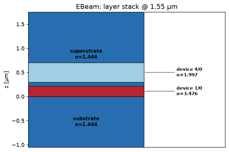
The layer stack of examples/tech.yaml: a silicon core on an oxide
substrate, clad in oxide. plot_tech_stack(tech) draws it from the file.
The technology file
Define each material once and reference it by name; layers place those materials
in z:
technology:
  name: "EBeam"
  schema_version: 2

  materials:
    Si:
      nk: 3.476                        # neutral constant (beamz, grid/modes)
      tidy3d: [cSi, Li1993_293K]       # tidy3d's dispersive model
      lumerical: Si (Silicon) - Palik  # Lumerical's dispersive model
    SiO2:
      nk: 1.444
      tidy3d: 1.444
      lumerical: SiO2 (Glass) - Palik
    SiO2_rii:                          # silica pinned to a measured model:
      nk: 1.444                        # `source: rii` makes EVERY engine
      tidy3d: 1.444                    # build it from the same
      lumerical: SiO2 (Glass) - Palik  # refractiveindex.info page
      rii: {shelf: main, book: SiO2, page: Malitson}
      source: rii

  substrate:   {z_base: 0.0, z_span: -2, material: SiO2_rii}
  superstrate: {z_base: 0.0, z_span: 3,  material: SiO2}
  pinrec: [{layer: [1, 10]}]           # port pins
  devrec: [{layer: [68, 0]}]           # device region (simulation bounds)
  device:
    - {layer: [1, 0], z_base: 0.0, z_span: 0.22, material: Si, sidewall_angle: 85}
examples/tech.yaml is the reference file. Load it with
Technology.from_yaml:
from gds_fdtd.technology import Technology

tech = Technology.from_yaml("examples/tech.yaml")
print(tech.name, "-", len(tech.device), "device layer(s)")
Bad values fail at load with the offending key named.
Materials: three sources of optical constants
This is where accuracy is won or lost. A material may name up to three sources of optical constants, and each engine picks exactly one at run time, so the same material serves every solver:
source |
what it is (tech-file key) |
engines |
|---|---|---|
|
the engine’s own database model, |
tidy3d, Lumerical |
|
a refractiveindex.info page ( |
all three |
|
a single constant index ( |
all three |
You do not have to specify all three. A material with only tidy3d and
lumerical gets each vendor’s dispersive model; add rii for one measured,
engine-independent model across all engines, or just nk for a quick
constant.
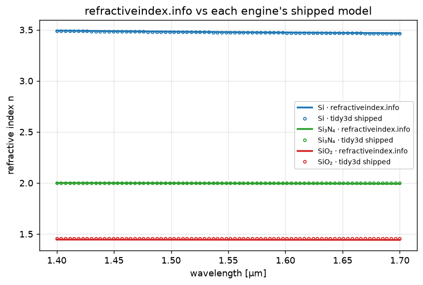
The engines’ shipped models (markers) sit on the refractiveindex.info data
(lines) for Si, Si₃N₄, and SiO₂, so an rii source and an eda source
agree to a few parts in ten-thousand. Reproduced in
02 · Technology & materials.
Which source each engine uses
If the material sets
source:explicitly (eda/rii/nk), that source is used, and it is an error if that source is not defined for the engine you are running.Otherwise the precedence is eda → rii → nk: the first one defined (and applicable to the engine) wins.
If none applies, a clear
MaterialSourceErroris raised, for example a Lumerical-only technology run on tidy3d.
beamz has no vendor material database, so its eda slot is always empty;
it uses rii (if present) or nk.
materials:
  Si:
    nk: 3.476                            # constant fallback (and beamz)
    tidy3d: [cSi, Li1993_293K]           # tidy3d's own dispersive model
    lumerical: Si (Silicon) - Palik      # Lumerical's own dispersive model
    rii: {shelf: main, book: Si, page: Salzberg}   # refractiveindex.info
    source: rii     # OPTIONAL: force every engine to use the rii model
                    # (omit -> tidy3d/Lumerical use their model, beamz uses rii)
The reference examples/tech.yaml demonstrates the pinning live: its
substrate material (SiO2_rii) carries all three sources and sets
source: rii, so the buried oxide comes from the Malitson (1965) Sellmeier
page on every engine. Engines that build a pinned material read the database
from disk — set GDS_FDTD_RII_DB (the examples ship a mini-DB under
examples/02_technology/rii_db). 02b · One refractiveindex.info model, every engine walks
through the selection with select_source().
How each engine applies the chosen source:
tidy3d:
edaandriiboth become dispersive media (riiis fitted to a pole-residue medium viato_tidy3d_medium());nkbecomes a constanttd.Medium.Lumerical:
edais the vendor database name (its own dispersion);rii/nkare emitted as an(n, k)material in the.lsf.beamz: a single constant index from
rii(sampled at band center) ornk.
Using refractiveindex.info directly
The point of rii is that one measured model, its full complex
n(λ) + i·k(λ), flows into every engine intact. rii pages are read
offline from a local copy of the refractiveindex.info database; point
GDS_FDTD_RII_DB at its data directory (or pass db_dir=):
from gds_fdtd.materials.rii import load_rii_material

au = load_rii_material("main", "Au", "Johnson")   # strongly dispersive + lossy
medium = au.to_tidy3d_medium()                    # -> a dispersive td.Medium
n, k = au.n_at(1.55), au.k_at(1.55)
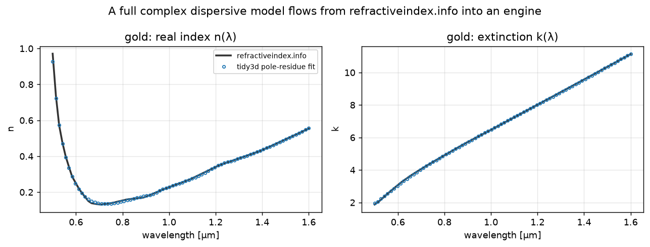
A measured gold model from refractiveindex.info (lines) and its tidy3d pole-residue fit (markers), across the full complex dispersion. Reproduced in 02b · One refractiveindex.info model, every engine.
The Si₃N₄ trap
A material name is not one number. “Si₃N₄” spans a family: LPCVD
stoichiometric nitride sits near n ≈ 2.0, while higher-nitrogen PECVD
films run ~0.4 higher. Match the variant to your fab, not just the formula.
Layers
Each layer places a material in z (µm), with positive z_span growing up
and negative growing down.
key |
meaning |
|---|---|
|
a list of patterned layers, each |
|
the backgrounds below and above the device, filled by the technology (not
the GDS): |
|
the GDS layer(s) carrying the port pins, where ports are detected. |
|
the GDS layer marking the device region; its bounding box sets the simulation extent. |
The frontend rasterizes these into the permittivity grid the solver integrates:
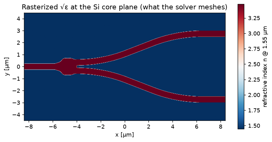
plot_permittivity(component, axis="z", position=0.11), the √ε map at the
Si core plane. This is the most useful FDTD sanity check: is the meshed
structure the one you intended?
Loading and using a technology
tech = Technology.from_yaml("examples/tech.yaml")

# inspect
tech.name, tech.device[0].z_span, tech.superstrate.material

# the plain-dict form the engine adapters consume (layers + resolved materials)
layers = tech.to_solver_dict()

# visualize the stack straight from the file (offline)
from gds_fdtd.plotting import plot_tech_stack
plot_tech_stack(tech, wavelength_um=1.55)
Migrating a schema-v1 file
Older files used per-layer inline materials (schema v1). Convert one to the named-material v2 form with the CLI (the two schemas are equivalent, v2 expands into v1 before validation):
gds-fdtd convert-tech old.yaml -o tech.yaml
Common issues
- MaterialSourceError at run.
The engine you ran has no usable source for a material, e.g. a Lumerical-only technology run on tidy3d. Add an
nkorriifallback, or the missingtidy3d:/lumerical:entry.- Ports not detected.
Check that the layout’s pins land on the
pinreclayer and the device region ondevrec. Ports come from those layers; see Layout Frontends.- Structure looks wrong in the field.
Plot
plot_permittivitybefore running. Wrongz_base/z_spansign (up vs down) or a GDSlayerthat doesn’t match the file are the usual causes.
See also
02 · Technology & materials and 02b · One refractiveindex.info model, every engine , the executed materials notebooks.
gds_fdtd.technology,gds_fdtd.materials.rii,gds_fdtd.materials.select, the API.Layout Frontends, how a layout is extruded against this technology.